PARTS
1 JOVE 20.1 receiver JOVE
1 GYRATOR 24 KHZ RECEIVER AAVSO
1 WHIP ANTENNA PART NO. 21-903 RADIO SHACK
1 LOOP ANTENNA radio shack
1 MINI AMPLIFIER PART NO. 277-1008 RADIO SHACK
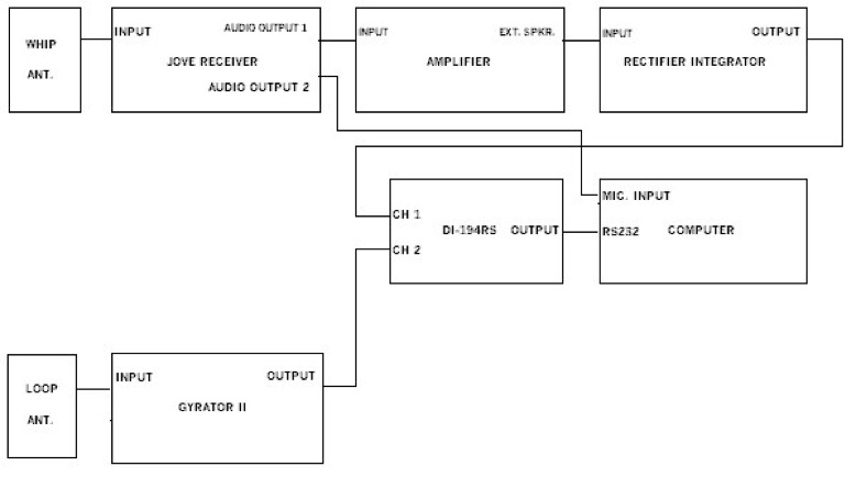
JOVE RECEIVER
All the components were mounted on a 24" by 10" white shelving board. Hook everything up per the above drawing, using 1/8" mono plug cables, except for the antenna inputs.
The JOVE receiver was assembled and calibrated per the supplied instructions. The only difference was a Radio Shack plug in power supply instead of a battery, Radio Shack PART NO. 273-1775.Get the M adapter plug with the power supply, make sure the plug is installed with the tip positive.
The only difference was a Radio Shack plug in power supply was added, Radio Shack PART NO. 273-1767. Get the F adater plug with the power supply, make sure the plug is installed with the tip positive.
A 1/4" hole was drilled 5/8" down and 3/8" from the left, on the top left corner of the PC board, for an audio connector for the power supply, like the ones already used on the board.
The whip antenna for the JOVE receiver is a Radio Shack 102" steel antenna, PART NO. 21-903. A 50' lead in cable, Radio Shack PART NO. 278-971, was used.
Cut one of the Pl-259 plugs off and replace with an F connector, Radio Shack PART NO. 278-277, so that it can be connected to the JOVE receiver. The antenna was mounted on an inverted plastic flower pot.
The amplifier is a mini amplifier from Radio Shack.
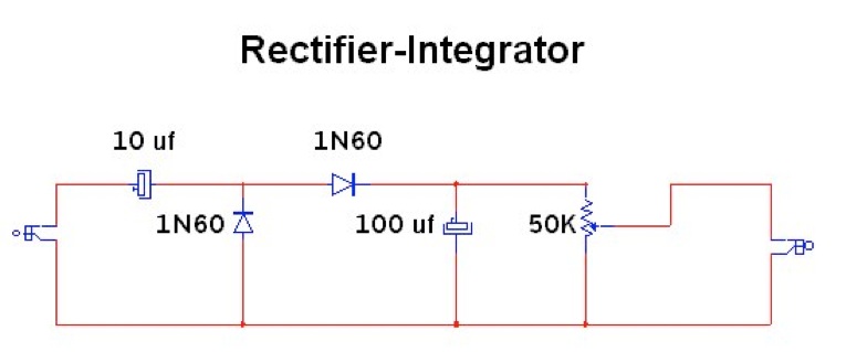
Rectifier-Integrator
The rectifier-integrator was assembled in a Radio Shack enclosure, part no. 270-1803, with audio connector input and output jacks. 1N914 diodes can be used , if you can not find the 1N60 diodes.
LOOP ANTENNA
The loop antenna was designed using #14 stranded wire, similar to the one Casper Hossfield describes in the April 2002 AAVSO Solar Bulletin.
PARTS:
HOME DEPOT
4 1 1/4" PVC 27 3/4"
4 1 1/4" PVC 4 3/4"
1 1 1/4 " PVC 6"
3 1 1/4" PVC 90 DEG. ELBOW
1 1 1/4 " PVC TEE
4 1 1/4 " PVC END CAP
1 1 1/4" PVC CROSS
1 1 1/4" PVC MALE ADAPTER
1 1 1/4" GALVANIZED FLOOR FLANGE
1 2' BY 2' 3/4' PLYWOOD
1 500' #14 STRANDED COPPER WIRE
RADIO SHACK
1 BOX PART NO. 270-1801
1 BARRIER STRIP PART NO. 274-656
1 SO-239 CHASSIS SOCKET PART NO. 278-201
1 50' CABLE PART NO. 278-971
1 1/8" MONO PLUG PART NO. 278-227
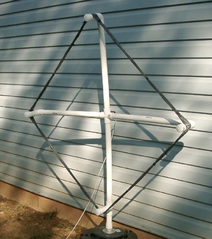
LOOP ANTENNA ASSEMBLY
When connecting the PVC lightly sand both ends before applying PVC cement.
Install the four 27 3/4" 1 1/4" PVC to the cross.
Install the tee, as per the picture, to one of the 27 3/4" sections. On the bottom.
Install the three elbows, as per the picture, to the three remaining 27 3/4" sections.
Install the 4 3/4" PVC to the elbows, and the tee.
Install the 1 1/4" caps, do not cement the one on the tee at this time. This is so you can have access to the wires when pulling then to the center of the cross.
Install the 6" PVC to the bottom of the tee.
Install the male adapter to the bottom of the 6" PVC.
Install the floor flange to the center of the 2' by 2' plywood.
Drill a hole, in the 4 3/4" section connected to the tee, large enought to push the #14 wire through, next to the tee, on the underside. Also drill one next to the cap, on the underside.
Feed about 4' of the #14 wire into the hole next to the tee, this will be pulled up to the center of the cross, on the inside of the PVC .
Wrap the #14 wire around the 4 3/4" sections 21 times. Cut wire leaving about 4' to feed into the hole next to the cap.
Feed the 4' of the #14 into the hole next to the cap, on the tee 4 3/4" section.
Drill a hole large enough to pull two #14 wires in the back center of the cross.
Push the wires on the inside of the PVC up to the center of the cross, do this through the male adapter, pull the wires out the hole in the back center of the cross.
Cement the cap on the 4 3/4 tee section.
Screw the antenna assembly to the floor flange on the plywood 2' by 2'.
Mount the barrier strip on the inside bottom of the box, 3" length of the box, with super glue.
Drill a hole in the bottom of the box, above the barrier strip, to bring the two #14 wires from the cross, into the box. Pull the two #14 wires into the box, cut and hook up to the barrier strip.
Super glue the box to the cross.
Mount the SO-239 socket on the lid of the box so that it does not hit the barrier strip when installed on the box. Wire the socket to the antenna wires on the barrier strip.
For 24 khz use .0276 ufd of capacitance to tune the loop. Hook this across the antenna leads on the barrier strip.
Cut off one of the PL-259 plugs on the 50' lead in cable, and install the 1/8" mono plug. This will plug into the Gyrator II receiver.
Capacitance to tune the loop for other frequencies.
khz ufd
21.4 .0346
24 .0276
24.8 .0257
26.1 .0233
27 .0218
30.6 .0166
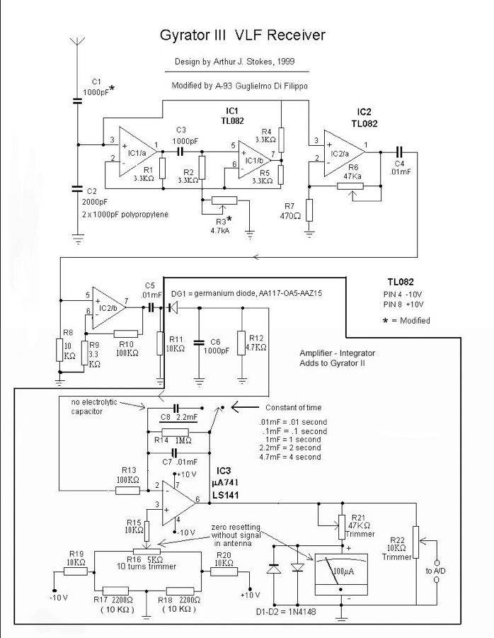
GYRATOR 24 KHZ RECEIVER
The GYRATOR lll receiver was assembled per the instructions on the AAVSO
web site. Get the pc board from FAR circuits, makes life a lot easier.
ANTENNA'S
Install the LOOP antenna and the Whip antenna outside alway from the buildings and power lines. Align the LOOP antenna with NAA in Cutler, Maine for 24 khz operation.
Run cables inside with the LOOP going to the GYRATOR IIl and the whip to the JOVE.
CALIBRATION AND OPERATION
Turn everything on, JOVE, amplifier, GYRATOR IIl, computer, and let them warm up.
Start DATAQ WinDaq 194 program.
Click View,Format Screen, 2Waveforms.
Click Edit,Sample Rate. Input 100 for sample rate.
Click OK.
On the JOVE system adjust the Rectifier-Integrator pot to full counter clockwise..
Set JOVE volume control at 10 o'clock. Tuning at 12 o'clock.
Adjust the mini amplifier volume control so there is about 3.5 volts on channel 1.
On the GYRATOR IIl system set the 10K tuning pot all the way clockwise, and the 50K gain pot all the way counter clockwise. Adjust the tuning pot slowly counter clockwise, until a voltage increase can be seen on channel 2.
Adjust the pot slowly back and forth until the maxium output is obtained, this should be about 5.5 volts to 6 volts. It is now tuned to 24 khz. Turn the 50K gain pot clockwise until there is about 3.5 volts on channel 2.
Click Scaling, Limits. Input channel 1 top limit at 6, and bottom limit at 0.
Click next. Input channel 2 top limit at 6, and bottom limit at 0.
Click OK.
Click Options,scroll mode.
Click edit, Sample Rate. Input 1 for sample rate.
Click OK.
Click File,Save Default Setup.
Click File, Record. Input file name.
Click Open.
The file size can be adjusted for a longer or shorter run at this time.
Click OK.
ENJOY